
radius gauge template set sounds simple, until you try to match an unknown fillet on a part and every leaf “almost” fits, which usually means wasted time, bad assumptions, or a tolerance surprise later.
If you’re in machining, fabrication, QA, or product design, a good radius gauge and template kit can save real hours, especially when drawings are missing, legacy parts show up, or you need quick verification at the bench without setting up a CMM.
This guide focuses on what actually matters in day-to-day use: which set to buy, how to get consistent readings, when a template is enough, and when it’s smarter to step up to more precise metrology.

What a radius gauge & template set actually does (and what it doesn’t)
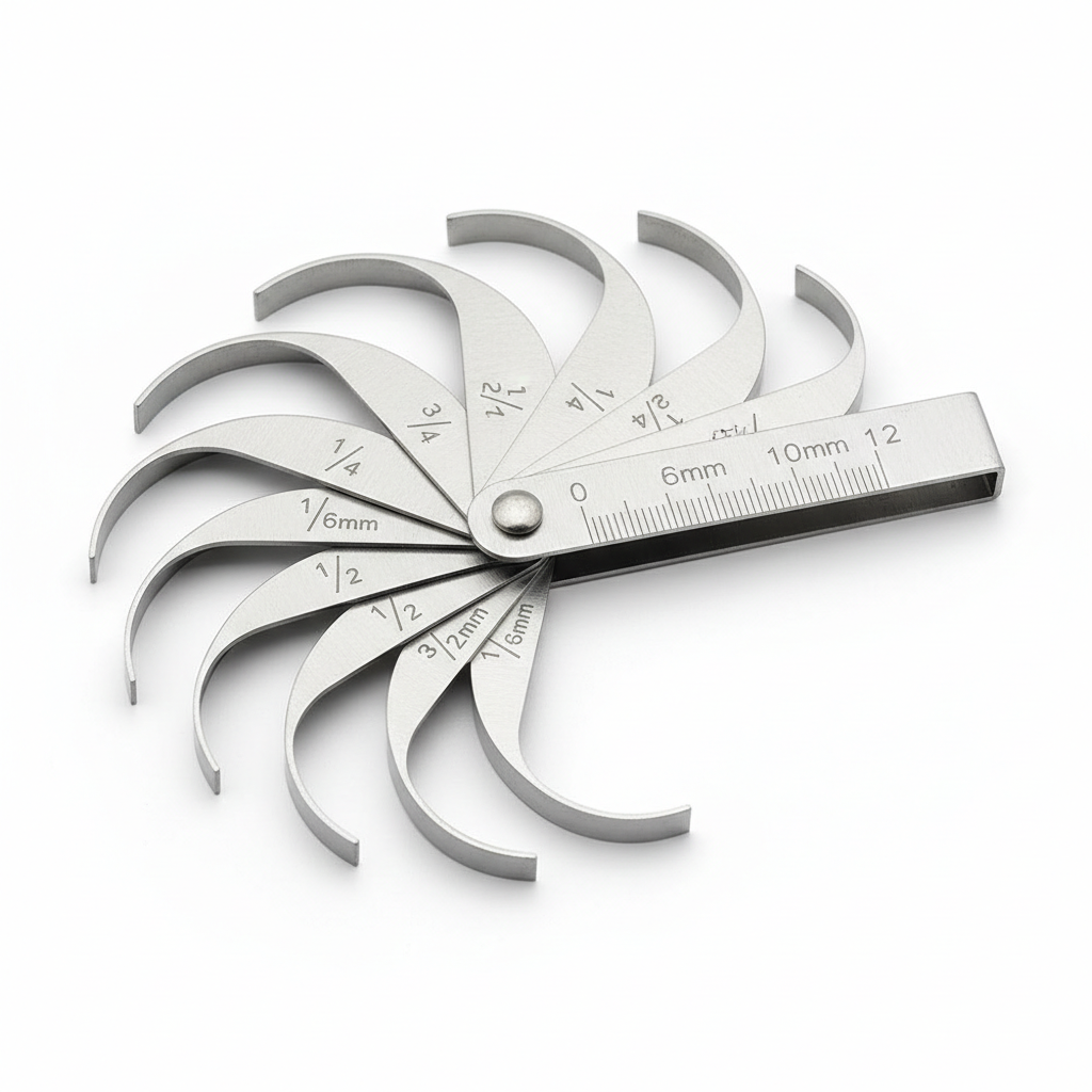
A radius gauge template set is a collection of pre-cut concave and convex radii, typically as “leaves” on a ring or as thicker plastic/metal templates. You press the curve against an edge or corner and look for the best match.
It’s fast, tactile, and usually accurate enough for many shop-floor checks, but it’s still a comparative method. That matters: you’re confirming “this looks like R0.125” more than you’re proving “this is R0.1250 within 0.0005.”
- Great for: quick inspection, setup verification, reverse-engineering, confirming a tool radius, checking deburring/edge blend consistency.
- Not ideal for: tight tolerance radii, worn surfaces, painted/coated edges, soft materials that deform under pressure.
According to NIST, measurement quality depends heavily on traceability and uncertainty management, which is a good reminder that “good enough” depends on your tolerance stack and risk level, not just the tool you have in hand.
Why “no leaf fits” happens: common root causes in real shops
When users say their radius gauges never fit, it’s rarely because the set is “bad.” More often it’s the surface, the method, or the expectation.
- Edge condition: burrs, paint, plating, bead-blast texture, or dings can hide the true radius.
- Blend vs true radius: many corners are “eased” by sanding or deburring, creating a blended curve rather than a single constant radius.
- Tooling marks: chatter or scallops from machining can break contact and trick your eye.
- Wrong reference: measuring an internal corner when you need external, or reading the leaf label upside down is more common than people admit.
- Unit mismatch: inch vs metric sets look similar in the small sizes, and that can waste a lot of time.
Saying it plainly: this tool rewards patience and a clean edge, and it punishes rushed “good enough” fits when the spec is tight.
Quick self-check: are you using the right set for your work?
Before you change your process, do a quick reality check. In many cases, the issue is simply that the kit range or increments don’t match what you build.
- Do your drawings call out radii in inch (R1/64, R1/32) or metric (R0.5, R1.0)?
- Are you checking mostly small fillets (under 3 mm / 1/8 in) or large blends?
- Do you need both convex and concave leaves?
- Do your parts have coatings, anodize, or paint where a thin leaf might slip under an edge lip?
- Does your team need “go/no-go speed,” or do you need documentation for QA?
If you answer “I’m not sure” to more than one of these, that’s usually the cue to standardize what set lives at each station and how you record results.
Choosing a radius gauge template set: what to look for
Specs can feel repetitive across listings, so here’s what tends to separate a frustrating kit from a reliable one in day-to-day use.
Material and edge quality
Stainless steel is common because it holds shape and resists corrosion. The practical detail: cleanly finished edges matter because rough edges can “hang” on burrs and give false confidence.
Range and increments
Small increments help when you’re trying to distinguish close sizes, but they also increase the chance you’ll convince yourself a near-fit is correct. Pick increments that match your tolerance expectations.
Readable markings
Look for deep engraving or clear etching. Printed markings wear off, and that becomes a training problem later.
Form factor
- Leaf sets: flexible, fast, easy to store, good for most bench checks.
- Template blocks/plates: stiffer, sometimes easier for trainees, useful for repeat checks on the same few radii.
Calibration expectations
A radius gauge template set is often treated as a shop aid rather than a calibrated instrument. If you’re in a regulated environment or your QA system requires it, talk with your quality lead about whether these need verification against known standards.
How to use radius templates for a cleaner, more repeatable match
radius gauge template set usage is mostly technique. A few small habits make results more consistent, especially when multiple people measure the same feature.
- Prep the surface lightly: remove burrs and debris; don’t “improve” the corner with extra sanding if you’re inspecting.
- Use backlighting: hold the part and leaf so light shows gaps, a thin halo makes mismatch obvious.
- Rock, don’t press: gentle rocking finds the best contact; heavy pressure can flex thin leaves and fool your eye.
- Check both directions: rotate the leaf slightly; a true radius tends to match consistently across small changes in angle.
- Confirm with a neighbor size: if R3.0 looks right, try R2.5 and R3.5 quickly to avoid “confirmation bias.”
If you need documentation, write down the best-fit size plus a note like “slight daylight at ends” instead of forcing a binary pass/fail that doesn’t reflect the surface reality.

Templates vs other methods: a practical comparison
Sometimes the right move is not “buy a better set,” but “use the right tool for the callout.” Here’s a quick, shop-friendly comparison.
| Method | Best for | Limitations | Typical use case |
|---|---|---|---|
| Radius gauge template set | Fast matching of common radii | Comparative, depends on surface condition | Setup checks, incoming inspection triage |
| Calipers + geometry | Rough estimation when access is good | Hard on small/inside radii, easy to misread | Field checks, quick sizing for tooling |
| Optical comparator / vision system | Profile inspection, small features | Setup time, line-of-sight requirements | First-article verification |
| CMM / scanning | High confidence, reporting | Time, cost, programming effort | Critical radii with tight tolerances |
According to ASME, GD&T interpretation and inspection method should align with the drawing requirement, which is another way of saying: match the metrology effort to the risk.
Common mistakes and how to avoid them
Most wasted effort comes from a few predictable traps. Fixing these makes any radius gauge set feel “more accurate,” without buying anything.
- Measuring a chamfer like it’s a radius: if the corner has a flat, you’ll never get a clean match.
- Ignoring wear: worn tools and worn parts can both shift contact; if the edge is visibly rounded from use, treat results as approximate.
- Using the wrong leaf side: concave vs convex is easy to mix up when you’re moving fast.
- Reading without light: overhead lighting can hide gaps; a flashlight from behind is a cheap upgrade.
- Assuming the drawing radius equals the produced radius: cutter comp, tool wear, and finishing steps can change the actual feature.
Key takeaway: when the fit feels subjective, your process needs a secondary check, even if it’s just “try adjacent sizes and note the daylight.”
When you should escalate to a pro measurement approach
A radius gauge template set is a smart first pass, but there are times it’s not the responsible stopping point.
- You’re dealing with a safety-critical part or regulated documentation where uncertainty must be controlled.
- The tolerance is tight enough that “best fit” could flip a pass to fail.
- The radius is part of a functional fit, like sealing surfaces or bearing transitions.
- Multiple operators get different answers, even after you standardize technique.
In those situations, it’s reasonable to involve QA metrology, a calibrated optical method, or a qualified inspection lab. If you’re unsure what your quality system expects, it’s worth asking your quality manager or an outside metrology professional.
Practical workflow: a repeatable way to check radii in minutes
If you want something your team can follow without overthinking, this lightweight workflow works in many shops.
- Step 1: Confirm unit system and expected callout from the print or spec note.
- Step 2: Clean the edge just enough to remove burrs and debris.
- Step 3: Match with the suspected radius, then verify with one smaller and one larger leaf.
- Step 4: Use backlight to judge gaps; avoid pressing hard.
- Step 5: Record best fit plus any nuance (surface texture, blend, coating).
- Step 6: If the result affects acceptance, confirm with a higher-confidence method.
It’s not fancy, but it reduces the “tribal knowledge” problem where only one person can get a consistent reading.
Conclusion: keep templates for speed, but be honest about certainty
A good radius gauge template set earns its place because it’s fast and practical, especially for inspection triage and everyday setup checks. The win comes when you pair it with a simple technique standard, good lighting, and a clear rule for when to escalate.
If you want a next step, pick one common part, run the workflow above with two operators, and see where disagreement starts, that’s usually the exact point you need either better surface prep, clearer acceptance language, or a different measurement tool.
FAQ
What is a radius gauge template set used for in machining?
It’s used to quickly compare an unknown radius on a part against known radii, typically for fillets, rounds, and internal corners during setup, inspection, or reverse-engineering.
How accurate is a radius gauge compared to a CMM?
A template set is usually a comparative check and can be quite repeatable on clean, true radii, but it won’t provide the same uncertainty control or reporting as a CMM, especially on tight tolerances.
Should I buy inch or metric radius gauges for a U.S. shop?
Many U.S. shops still run inch prints, but metric shows up often in imported equipment and some industries, so the practical answer is: buy what matches your drawings, and consider a dual set if you regularly see both.
Why do I see light gaps even when the radius looks correct?
Light gaps often come from surface texture, a blended edge rather than a constant radius, or a slightly different radius than the leaf increment. Trying the neighboring sizes helps confirm what you’re seeing.
Can radius gauges measure plastic or wood parts?
They can, but soft materials may deform under pressure, so keep the touch light and treat results as approximate unless you confirm with another method.
Do radius gauge sets need calibration?
In many shops they’re treated as reference tools, but some quality systems may require verification. If your work is regulated or audited, ask QA what documentation is expected.
What’s the difference between concave and convex radius gauges?
Concave leaves check external rounds (outside corners), while convex leaves check internal radii (inside corners). Mixing them up is a common reason for “no fit.”
If you’re trying to standardize inspections across shifts, or you keep seeing disputes about what radius “counts,” a small step like choosing one consistent radius gauge template set per station and writing a one-page check method can make the whole process calmer and faster.